- +27 79 866 5061
- pitso.masooa@resatech.co.za
Of all the major asset classes on electricity networks, MV and HV cables are regularly shown to have a high contribution to overall network risk and significantly impact network performance. To effectively manage high voltage electricity networks, owners and operators have a very real need to properly understand the condition of their assets. Inspection and commissioning of newly installed MV and HV equipment, especially for the power transmission and distribution network is an important procedure to ensure reliability and performance of the power system. The assessment of ageing and preventing damages of MV and HV cable systems is highly important for the utilities today. Due to the quality of the power distribution network and the high cost of increasing demand for reliability in the power supply, MV and HV cable systems need more performance testing and control. Since many years HVDC and HVAC testing at power frequency under laboratory and field conditions have been reliable tools for insulation condition assessment. Pressure testing or Hi-Pot testing has often been used on HV cables, particularly as part of commissioning. Although useful in the commissioning phase it is not a good method for detecting insulation defects or providing useful condition information.
The introduction of VLF testing technique has greatly improved the efficiency of offline testing of MV and HV power cables. The traditional method for the measurement of PD has been to take the cables off-line and energise using a power supply operating at Very Low Frequency (VLF). A typical VLF test set used for PD mapping of MV and HV cables will often have integrated tan delta diagnostic capability so both tests can be carried out during the same session.
• Partial discharges inside the cable cause a short-term breakdown of the cable insulation.
• The thereby caused pulse-shaped recharging current is detected at the coupling capacitor over the measurement unit (quadrupole) - in parallel to the cable.
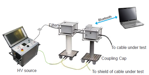
• This current signal is then converted into an equivalent voltage signal.
• The voltage signal is then recorded by the partial discharge detection system and monitored as an impulse on the monitor.
• PD pulses contain high frequency components.
• HF Components do not flow through the HV source as it is largely inductive and has high Z.
• The HVCC provides low impedance path for these high frequencies allowing PD current pulses to be measured by the measuring impedance (Zm).
• If the insulation of a cable is free from defects, like water trees, electrical trees, moisture, and air pockets, etc., the cable approaches the properties of a perfect capacitor.
• It is very similar to a parallel plate capacitor with the conductor and the neutral being the two plates separated by the insulation material.
• In a perfect capacitor, the voltage and current are phase shifted 90 degrees and the current through the insulation is capacitive.
• If there are impurities in the insulation, like those mentioned above, the resistance of the insulation decreases, resulting in an increase in resistive current through the insulation.
• It is no longer a perfect capacitor. The current and voltage will no longer be shifted 90 degrees.
• The phase shift between the two will be something less than 90 degrees.
• The extent to which the phase shift is less than 90 degrees is indicative of the level of insulation contamination, hence quality and reliability.
• This “Loss Angle” is measured and analysed and is called Tan Delta (Tan δ), sometimes referred to as the Dissipation Factor.
• The cable to be tested is first de-energized and each end isolated.
• The voltage is applied between the cable core and the outer sheath while the controller takes measurements
• Typically, the applied test voltage is raised in steps, with measurements first taken up to 1U0, or normal line to ground operating voltage.
• If tan δ numbers indicate good cable insulation, the voltage is raised up to 1.5 to 2U0 for aged cable systems and up to 3U0 for new cables.
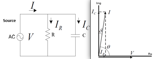
• The tangent of the angle δ is measured, this will indicate the level of resistance in the insulation.
• By measuring IR/IC (opposite over adjacent – the tangent), we can determine the quality of the cable insulation.
• In a perfect cable, the angle would be nearly zero.
• An increasing angle indicates an increase in the resistive current through the insulation, meaning contamination.
• The greater the angle, the worse the cable.
• It is expressed in V/mm.
• It is the maximum electric field strength that an insulation material can withstand without breaking down.
• Experimental Determination
It
It
It
It
It
It
It
It
It
It
It
It
It
It
It
It
It
It
It
• It is expressed in V.
• It is a standard value of voltage predetermined to validate the strength of a given insulation material.
• Tests and Standards
• Much of the testing is done on a comparative basis, established levels do not exist for all cable types, accessories, and varying installation methods - there is no reliable consensus on what are good versus bad Tan δ levels.
• The main purpose of the test is to grade all cables tested on a scale from high quality to low. The point in the testing is to help a utility prioritize cable replacement or rejuvenation.
• Comparative testing will show which cables are worse than others and will, over time, permit the user to develop their own in-house guidelines, unique to their situation.
• Since test voltages of up to 2Uo are used, there is a possibility of a cable failing during the few minutes needed to perform the test however, since the test takes only 5 – 10 minutes, the cable is not voltage stressed for a long enough period for breakdown to occur, unlike a VLF AC hi-pot test where up to 3 times normal voltage is applied for at least 30 minutes.
• It is generally advantageous to test shorter lengths rather than a long cable, because the shorter the section of cable that is tested, the more precise it can be in determining where the cable is good or bad.
• Tan delta tests the cable from point A to point B and gives an assessment of the insulation quality between those points. For any value of tan delta, there could be many minor defects or a few major defects.
• Since we are measuring the loss angle of an insulating material and making an analysis about the test results based on historical data, it is not advisable to test a cable length that contains more than one type of cable.
• Different cables have different loss characteristics. It is not a good practice to test a cable length of XLPE insulation spliced to an EPR or PILC cable.
• Since we are measuring the loss angle between the conductor and the outer shield, the outer shield must be intact. It is advisable to test the integrity of the concentric neutral before performing the test. (This is a worthwhile test anyway for several reasons, whether a tan delta test is being performed or not).
• If there are large gaps in the neutral, the tan delta numbers will not be meaningful.
• There are two main reasons why the VLF is preferred over the normal power line frequency: